
Kinetico Water

Top 10 Types of Insulated Terminal Lugs for Wiring?

Reliable wiring begins with a small connection that is often overlooked: the terminal lug. Insulated Terminal Lugs protect crimped conductors from accidental contact, moisture, vibration, and short circuits. In a control cabinet, that protection can be as practical as preventing a loose copper strand from touching a metal enclosure. The choice still depends on conductor size, insulation material, temperature rating, and installation conditions.

MarketsandMarkets’ 2024 Wire and Cable Market report estimates the global market at more than USD 200 billion, with continued growth driven by power networks, automation, renewable energy, and electric vehicles. This expansion increases demand for dependable connection hardware. However, wire growth does not automatically guarantee safe terminations. The International Electrotechnical Commission’s IEC 61238-1 standard emphasizes electrical and mechanical performance for compression and mechanical connectors. UL Solutions also highlights proper crimping, material compatibility, and application-specific testing.

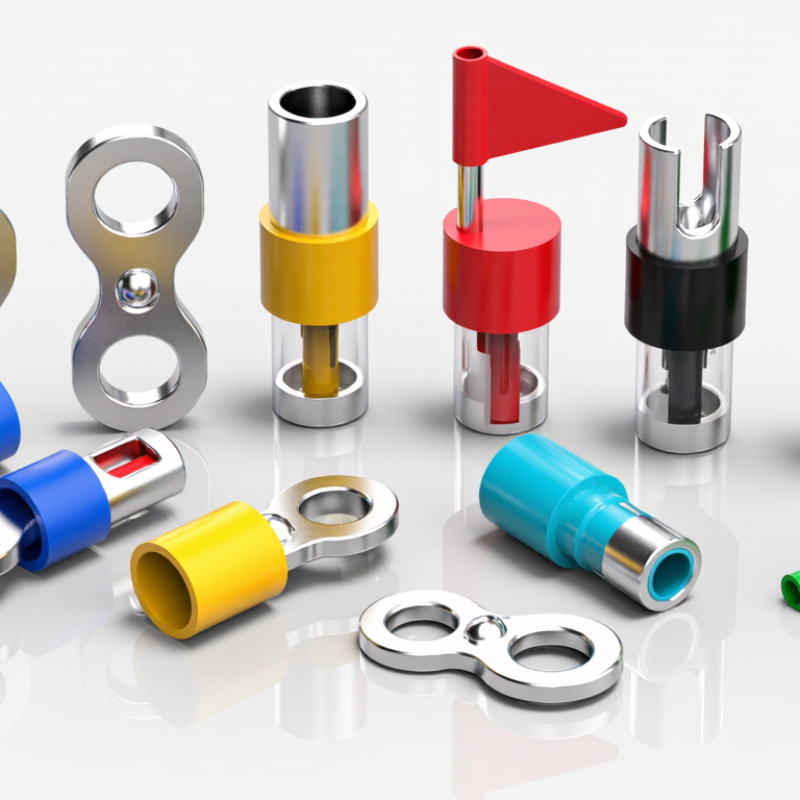
That is where this guide becomes useful. It examines ten common types of Insulated Terminal Lugs, including ring, fork, pin, butt, and flag terminals. Each design creates a different balance between installation speed, vibration resistance, serviceability, and current capacity. A ring terminal may remain secure under repeated movement, while a fork terminal allows faster removal during maintenance. Neither choice is universally superior. That point is easy to miss.

Real installations are rarely perfect. Crimp height may vary, tools may wear, and insulation can become brittle near heat sources. Therefore, this overview combines manufacturer guidance, recognized standards, and practical wiring experience. It also encourages careful verification before production use. A suitable lug is not merely one that fits the wire. It must fit the entire electrical environment.
Top 10 Types of Insulated Terminal Lugs for Wiring?

How Insulated Terminal Lugs Are Classified by Connection Method

Insulated terminal lugs are often grouped by shape, but connection method gives electricians a more useful classification. A practical ten-type taxonomy includes crimp, compression, solder, screw-clamp, set-screw, bolted, spring-clamp, push-in, insulation-displacement, and quick-disconnect lugs. Each method changes installation speed, pull-out strength, vibration resistance, and inspection requirements.

Crimp lugs use a controlled die to deform the barrel around the conductor. Compression lugs usually need heavier tooling and suit larger cables. Soldered lugs can seal fine strands, but heat may damage nearby insulation. Screw-clamp and set-screw designs simplify field work, although loose torque remains a real concern. Bolted lugs provide strong joints on busbars. Spring-clamp and push-in types support faster panel assembly. Insulation-displacement lugs pierce insulation directly, while quick-disconnect lugs allow repeated servicing. The connection is the deciding detail.

The International Energy Agency reported that global electricity demand could grow by about 4% in 2024 and 2025, increasing pressure on reliable wiring installation. IEC 61238-1 evaluates mechanical and electrical performance for power cable connectors, while UL 486A-486B addresses wire connectors and terminals. These standards do not make every lug interchangeable. Field experience proves that conductor material, barrel size, crimp profile, and torque must match. I have seen neat-looking joints fail after vibration because the tool was wrong. That shortcut still needs questioning. A transparent inspection record should note the lug type, conductor size, tooling, and applied torque.

Top 10 Types of Insulated Terminal Lugs for Wiring

Classification by the primary connection method used to attach the terminal to the conductor

Insulated terminals are commonly identified by their conductor-attachment method. Crimp terminals use mechanical compression, screw-clamp terminals use tightening force, solder terminals use melted solder, and insulation-displacement terminals cut through insulation to contact the conductor. The numeric positions represent connection-method categories, not performance ratings.

The Ten Main Types: Ring, Fork, Hook, Pin, Butt, Flag, Bullet, Spade, Parallel, and Ferrule

Top 10 Types of Insulated Terminal Lugs for Wiring

Insulated terminal lugs help secure conductors and reduce accidental contact. Ring terminals provide the most reliable hold on a stud. Their closed eye stays attached during moderate vibration. Fork terminals fit beneath a loosened screw, saving time during maintenance. Hook terminals offer similar access, but their open shape can slip if poorly tightened. Pin terminals enter narrow screw-clamp openings and keep fine strands organized.

Butt connectors join two wires end to end. A firm crimp should leave no exposed copper beyond the insulation. Flag terminals turn the wire sideways, making them useful in compact panels. Bullet terminals connect and disconnect quickly, often in harnesses that need repeated servicing. Check the mating pair carefully.

Spade terminals suit screw terminals and provide broad contact around the fastener. Parallel connectors join wires side by side, supporting branching or extending circuits when sized correctly. Ferrules compress stranded wire into a neat metal sleeve before insertion into a clamp terminal. This can reduce strand spreading and improve repeatable tightening. In field work, I have seen failures caused less by the lug type than by the wrong wire size, weak crimp pressure, or damaged insulation. A visual pull test is useful, but it is not perfect. For critical wiring, verify the crimp with the specified tool and inspect the conductor barrel closely.

Comparing Wire Ranges, Current Ratings, Voltage Ratings, and Temperature Classes

Top 10 Types of Insulated Terminal Lugs for Wiring

The ten common types include ring, fork, spade, hook, pin, blade, flag, quick-disconnect, butt-splice, and parallel-splice terminals. Each design suits a different installation condition. Ring terminals resist pullout, while fork terminals allow faster servicing. Pin terminals fit narrow screw clamps, and flag terminals help in crowded enclosures. Wire ranges often span 22–16 AWG, 16–14 AWG, 12–10 AWG, or larger sizes. However, the printed range is not a current rating.

Current capacity depends on conductor size, metal, crimp quality, insulation, and heat dissipation. NFPA 70, Table 310.16, lists 14 AWG copper at 15 amperes, 12 AWG at 20 amperes, and 10 AWG at 30 amperes under common 60°C conditions.

A terminal may carry less. UL 486A-486B and IEC 61238-1 require mechanical and electrical performance testing, but neither creates one universal rating for every lug. Check the terminal marking and the equipment specification.

Voltage ratings commonly appear as 300 V or 600 V, yet insulation thickness and spacing control suitability. Temperature classes may include 75°C, 105°C, or 125°C. Higher temperature capability does not automatically increase ampacity. I have seen oversized lugs fail after loose crimping. The mistake was small. A reliable selection matches wire range, current, voltage, temperature, and tool calibration. These details deserve a second look.

UL 486A-486B and IEC 61238-1 Requirements for Lug Performance

Top 10 Types of Insulated Terminal Lugs for Wiring

UL 486A-486B and IEC 61238-1 Requirements for Lug Performance

Common insulated lug types include ring, fork, hook, pin, butt, parallel splice, flag, bullet, ferrule, and quick-disconnect terminals. Each design suits a different wiring condition. Ring lugs resist accidental release under vibration. Fork lugs support faster maintenance. Ferrules improve stranded-wire entry into screw terminals. Insulation colors often indicate wire ranges, but color alone is not proof of compliance.

UL 486A-486B evaluates connector performance through crimp security, electrical resistance, temperature cycling, and mechanical strength. The lug must match the specified conductor size and crimp method. Insulation should remain secure without blocking the conductor barrel. In field inspections, uneven crimp marks often reveal poor tooling or unsuitable dies. Small errors matter.

IEC 61238-1 focuses on compression and mechanical connectors used with power cables. Its testing can include heating cycles, current performance, mechanical loading, and short-circuit behavior, depending on the applicable class and product scope. This standard is not automatically suitable for every small control-wire terminal. Check the declared application carefully. A catalog claim is not evidence. I have seen installations pass visual inspection yet fail after repeated thermal cycling. The overlooked detail was conductor compatibility. Better verification combines the standard, manufacturer instructions, calibrated tools, and documented pull-test results. Some assumptions remain uncomfortable, but they should be tested.

Selecting and Installing Lugs Using Crimp Profiles, Pull Tests, and Torque Data

Top 10 Types of Insulated Terminal Lugs for Wiring

Choosing among ring, fork, hook, pin, blade, flag, butt, parallel, closed-end, and quick-disconnect lugs requires more than matching wire size. The insulation rating, conductor material, terminal shape, and available space all matter. A ring lug resists accidental release, while a fork lug allows faster servicing. Pin lugs suit compact screw terminals. Use the terminal manufacturer’s specifications, not appearance alone.

Crimp quality depends on the correct die, barrel, and crimp profile. A polished crimp can still be wrong. The conductor should reach the inspection window without extending through the barrel. Insulation must remain supported without entering the conductor crimp area. A pull test should apply steady axial force, using the required value for that wire size and terminal class. If the lug slips, rotates excessively, or damages the strands, stop and remake it.

Torque applies to the terminal connection, not the crimp itself. Clean the contact surfaces, place the lug flat, and tighten the fastener with a calibrated torque tool. Record the final torque when the installation is safety-critical. Over-tightening can deform the lug or damage the stud. Under-tightening causes heat, loosening, and voltage drop. Temperature, vibration, and corrosion may also change performance. A visual check alone is not enough. I still allow a second inspection, because small alignment errors are easy to miss.

Top 10 Types of Insulated Terminal Lugs for Wiring? — Selecting and Installing Lugs Using Crimp Profiles, Pull Tests, and Torque Data

Insulated Terminal Lug Type Typical Wire Size Common Insulation Color Typical Stud or Mating Size Recommended Crimp Profile Example Pull-Test Target Typical Connection Torque Primary Selection and Installation Notes
Ring Terminal 22–16 AWG
(0.34–1.5 mm²)
Red M3–M4
(#4–#8)
Controlled B-crimp or manufacturer-specified insulated-terminal die At least 45 N for 22–16 AWG conductors when tested against the applicable terminal standard Typically 0.8–2.0 N·m for M3–M4 screw hardware Best for vibration-resistant connections because the ring cannot pull off when the screw is slightly loosened.
Fork or Spade Terminal 16–14 AWG
(1.5–2.5 mm²)
Blue M3–M5
(#4–#10)
Controlled B-crimp with insulation support At least 133 N for 16–14 AWG conductors, subject to the applicable test method Typically 0.8–3.5 N·m for M3–M5 screw hardware Allows faster installation than a ring terminal, but the open fork is less secure if the fastener is not fully tightened.
Pin Terminal 22–16 AWG
(0.34–1.5 mm²)
Red Terminal-block clamp opening; commonly 2.5–4 mm F-crimp or B-crimp, depending on barrel design At least 45 N for 22–16 AWG conductors Typically 0.4–1.2 N·m for small terminal-block screws Forms a compact end for terminal blocks and reduces strand spreading during insertion.
Fully Insulated Female Quick-Disconnect 16–14 AWG
(1.5–2.5 mm²)
Blue 6.3 mm blade, commonly 0.8 mm thick F-crimp or B-crimp with conductor and insulation wings supported At least 133 N for 16–14 AWG conductors Not applicable to the crimp; mating force is controlled by terminal design Use for removable connections. Confirm blade width, thickness, retention force, and insulation clearance.
Fully Insulated Male Quick-Disconnect 22–16 AWG
(0.34–1.5 mm²)
Red 6.3 mm blade, commonly 0.8 mm thick F-crimp or B-crimp with a calibrated hand tool At least 45 N for 22–16 AWG conductors Not applicable to the crimp; mating force is controlled by terminal design Pairs with a female quick-disconnect. Avoid twisting the terminal during insertion or removal.
Butt-Splice Connector 22–16 AWG
(0.34–1.5 mm²)
Red Not applicable Two separate conductor crimps using the specified barrel sections At least 45 N per conductor side for 22–16 AWG conductors Not applicable; the splice is mechanically crimped Joins two wires end-to-end. Strip length must match the barrel stop, and neither conductor should be visible beyond the inspection area.
Closed-End Cap Connector 22–14 AWG
(0.34–2.5 mm²)
Red or blue Not applicable Twist-on or compression crimp, only when permitted by the connector design Verify the applicable connector-specific pull test; a generic lug target should not be substituted Not applicable Used to cover and electrically join multiple conductors. Confirm conductor count, total cross-sectional area, and enclosure suitability.
Twin Wire Ferrule 2 × 18–16 AWG
(2 × 0.75–1.5 mm²)
White or red Terminal-block clamp opening; commonly 2.5–4 mm Square or hexagonal compression profile matched to the ferrule Test the complete two-conductor assembly; a typical engineering target is at least 100 N total, subject to the ferrule standard Typically 0.4–1.2 N·m for small terminal-block screws Terminates two conductors in one clamp. Both wires must be fully inserted and must have equal stripped lengths.
Insulated Butt-Splice with Heat-Shrink Seal 16–14 AWG
(1.5–2.5 mm²)
Blue Not applicable Indent, B-crimp, or hex crimp specified for the sealed barrel At least 133 N per conductor side for 16–14 AWG conductors before environmental conditioning Not applicable; the joint is mechanically crimped Provides strain relief and environmental sealing when correctly heated. Use the specified heat range without damaging insulation or sealant.
Insulated Ring Power Lug 12–10 AWG
(2.5–6 mm²)
Yellow M5–M6
(#10–1/4 in)
Indent or hex crimp using a die matched to the barrel and conductor size At least 311 N for 12–10 AWG conductors when verified using the applicable terminal standard Typically 2.0–5.0 N·m for M5–M6 screw hardware Suitable for higher-current wiring. Torque depends on the screw, nut, washer, material, and equipment connection—not the insulation color.
Technical notes: Wire-size colors are common industry conventions: red for smaller conductors, blue for medium conductors, and yellow for larger insulated terminals. Pull-test values shown are practical reference targets and must be confirmed against the governing terminal standard, conductor class, terminal construction, and applicable wire range. Connection torque applies to the mating screw or terminal hardware; always use the equipment or terminal-block manufacturer’s specified torque when available. A properly calibrated crimp tool and a complete visual inspection should be used before energizing the circuit.